
Views: 0 Author: Site Editor Publish Time: 2026-10-31 Origin: Site


Picture this: a massive production line grinds to a halt because a raw material batch is just three millimeters too wide. Such a tiny width error causes catastrophic machine jams and thousands of dollars in ruined metal. Roll forming requires exact material inputs to prevent costly scrap and ensure operational efficiency. In this comprehensive guide, you will learn how to calculate, select, and specify the perfect coil dimensions for your equipment from an engineering perspective.
Precision is Profit: Exact dimensions minimize metal scrap, prevent edge waving, and protect expensive roll tooling from premature wear.
Calculation is Key: Determining the flat pattern requires factoring in bend allowances, material thickness, and the specific neutral axis.
Machine Limits Matter: Uncoiler capacity, entry guide adjustability, and cutting mechanisms dictate the maximum and minimum sizes you can safely run.
Material Selection: Substrate choice depends entirely on environmental demands and forming severity.
For procurement managers and engineers, sourcing the correct raw material is the foundational step in manufacturing. In cold roll forming, the incoming steel dimension dictates the physical behavior of the metal as it passes through sequential forming stations.
When a batch is ordered wider than necessary, the excess material must go somewhere. Oversized sheets require inline edge trimming in specialized setups. This process generates continuous strips of razor-sharp scrap, directly reducing material yield and creating safety hazards on the shop floor. Over thousands of meters of production, even a five-millimeter overage translates to significant financial losses and severely diminished profit margins.
Roll forming dies are precision-engineered to accommodate a specific volume of metal. Feeding a sheet that is too wide forces the excess material violently against the vertical flanges of the roll dies. This creates severe lateral friction. Over time, this friction leads to galling—a destructive form of wear where material transfers between sliding surfaces. An operator might spend hours polishing galling marks off a forming roll simply because the purchasing department ordered material with a loose slitting tolerance. Such tooling degradation requires costly machine downtime for die polishing or complete replacement.
Metal follows the path of least resistance. Incorrect sizing means the material volume entering the forming passes does not match the engineered clearance between the top and bottom rolls. This mismatch causes uneven stress distribution across the sheet. The result is often severe profile distortion, manifesting as flare at the ends of the part, rippling edge waves along the length, or camber—a lateral bow rendering the finished product unusable.
Recent analyses of global metal fabrication trends reveal a sharp industry-wide focus on material yield optimization. With steel prices fluctuating unpredictably on the global market, manufacturers are moving away from traditional mill-edge materials. Instead, there is a massive shift toward highly precise slit edges. Furthermore, the rising demand for lightweight structural components has introduced Advanced High-Strength Steels into standard roll forming operations. These high-tensile materials exhibit extreme springback and are notoriously unforgiving to width variations. Consequently, modern roll forming facilities are upgrading their procurement standards, demanding slitting tolerances as tight as plus zero and minus zero point five millimeters to prevent catastrophic tooling damage and ensure uninterrupted throughput.
Determining the correct dimension is not as simple as taking a tape measure to the cross-section of the finished profile. The mathematical calculation must account for how metal stretches and compresses when deformed.
The flat pattern is the exact width of the unformed sheet required to produce the final profile. Engineers calculate this by breaking down the cross-section of the desired profile into straight segments and curved bends. The sum of these segments, carefully adjusted for material stretching, equals the required procurement dimension.
When steel is bent, the material on the outside of the radius stretches in tension, while the material on the inside compresses. The boundary line between tension and compression is called the neutral axis.
The location of this neutral axis is represented by the K-factor. Specifically, the K-factor varies depending on the material thickness, yield strength, and the inside radius of the bend. Failing to account for the K-factor results in a calculation that is too short, leading to undersized flanges on the final product. The core formula involves adding the sum of all straight sections to the sum of all calculated bend allowances.
Steel mills and service centers slit master coils into narrower bands. This mechanical slitting process has inherent tolerances. It is absolutely critical to communicate exact tolerance requirements to your supplier. If a batch arrives at the upper limit of a loose tolerance, it may instantly bind in your entry guides. Specifying precision tolerances ensures the material feeds smoothly without constant operator intervention.
The mechanical design of your machinery directly impacts how sensitive the process is to dimension variations.
In a pre-cut line, the flat steel is sheared to the desired length before it enters the forming stations. Because the material travels through the machine as individual, disconnected blanks rather than a continuous web, pre-cut lines require perfect edge conditions. If the blank dimension varies, the material can easily twist, skew, or misalign as it transfers from one forming pass to the next. This misalignment leads to unacceptably high rejection rates.
In contrast, post-cut lines feed a continuous web of steel through the forming stations, with a flying shear or cut-off press severing the profile at the very end of the line. The continuous tension helps keep the material naturally centered. While post-cut lines are generally more forgiving of minor variations, strict adherence to the specified dimension is still required to prevent the material from jamming in the entry guides or destroying the final cut-off die.
For cold-formed metal products, the substrate material must balance rigorous formability with long-term environmental resistance.
The hot-dip galvanizing process applies a robust layer of zinc to the steel substrate. This creates protective galvanized steel, which is highly favored in roll forming operations worldwide. The zinc coating serves a crucial dual purpose. First, it provides galvanic corrosion resistance, sacrificing itself to protect the underlying steel from rust. Second, the zinc layer acts as a mild, solid lubricant during the cold forming process. This lubricity significantly reduces friction between the sheet and the roll dies, extending tooling life.
The internal metallurgy dictates forming behavior. Commercial Quality steel has a lower yield strength, making it highly ductile and formable for complex, deep-drawn profiles. Structural Quality steel has a much higher yield strength. While this provides superior load-bearing capacity for structural components, it dramatically increases springback during forming. Operators must carefully match the material grade to the machine's forming capacity.
The required dimension is intrinsically linked to the end-use application and the complex geometry of the final panel design.
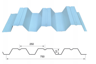
Roofing panels require specific dimensions to achieve standard architectural coverage areas. Common master sizes used in the roofing industry include 914mm, 1000mm, 1200mm, and 1250mm. The depth and frequency of the corrugations dictate how much flat material is consumed. For example, producing deep-rib profiles designed for galvanized steel roofing requires precise calculations. A standard YX 113-300-600 profile demands an exact feed width of 1000mm to yield an effective coverage of 600mm. This ensures the overlapping ribs interlock correctly during installation without short-changing the overall panel coverage.
When manufacturing architectural cladding, operators often use prepainted galvanized iron. Roll forming a finished color steel plate requires extra mechanical precautions. For instance, creating a wide-coverage YX 71-480-960 panel requires a precise 1200mm feed width. If the material is sized too wide, the entry guides or the vertical flanges of the roll dies will aggressively scrape against the painted edges. This friction causes the coating to peel, flake, or scratch, immediately exposing the bare metal to premature corrosion. Operators must ensure clearance tolerances are strictly maintained when running prepainted materials to preserve both the aesthetic beauty and the protective integrity of the paint system.
Even if the mathematical calculation for your flat pattern is flawless, the physical limitations of your machinery will ultimately dictate what materials you can actually process on the shop floor.
The uncoiler is the very first point of contact in your production line. While it must accommodate the physical size of the sheet, it must also support the massive weight and specific inner diameter. If a heavy batch exceeds the maximum weight capacity of the uncoiler, the mandrel shaft can deflect. This subtle bending causes uneven tension, making the material walk left or right as it feeds. Furthermore, the mandrel must be able to expand sufficiently to grip the specific inner diameter securely.
Entry guides act as the steering wheel for your roll forming line. They ensure the flat sheet enters the first forming station perfectly centered. If a sheet is too narrow, it will wander between the guides, causing asymmetrical flanges. If it is too wide, it will bind against the guides, causing the edges to buckle before the forming process even begins. Operators must verify that their entry guides have the mechanical travel range to accommodate the specified slit dimension.
The complexity of the profile and the dimension of the incoming material determine how many forming stations are required. Wider sheets being formed into deep, complex profiles require machines with a higher number of forming passes. This gradual deformation prevents the metal from stretching beyond its elongation limits, which would otherwise result in catastrophic tearing or microscopic cracking along the bend radii.
Procuring the correct raw materials is a high-stakes process. A minor miscalculation in specifications can lead to extensive machine downtime and unacceptable scrap rates. To bridge the gap between engineering requirements and supply chain execution, utilize this comprehensive purchasing checklist.
The most critical dimension in your order is the flat pattern. However, specifying a nominal number is insufficient; you must explicitly state the acceptable slitting tolerances. Ordering slit-edge material is standard practice. When specifying the dimension, define the tolerance bandwidth. It is generally safer to specify a negative tolerance. If a sheet is slightly too narrow, it may cause minor tracking issues that can be corrected; if it is too wide, it will forcefully bind and cause immediate machine damage.
The mechanical properties dictate how the steel will behave as it passes through the forming stations. You must specify the exact material type and its corresponding yield strength. Feeding high-strength steel into a machine designed for mild steel will cause severe tooling deflection and premature bearing failure.
Your uncoiler dictates the physical dimensions you can process. Uncoiler mandrels are designed to expand and grip the inside of the roll. If you order an inner diameter that is too large, the mandrel will slip; if too small, it will not fit. Additionally, the maximum outer diameter is limited by the distance from the center of the mandrel to the factory floor. Exceeding this limit will result in the material scraping the floor.
For applications requiring aesthetic appeal, surface finishes must be strictly defined. When ordering a color steel sheet for architectural applications, the procurement document must specify the exact paint system, the topcoat thickness in microns, and the primer specifications. For example, a YX 35-280-840 profile requires a 1000mm feed width to achieve its 840mm effective coverage, and the paint must possess sufficient flexibility to withstand tight bending radii without cracking.
Parameter | Specification Requirement | Engineering Impact on Roll Forming |
|---|---|---|
Material Grade | e.g., ASTM A653, Grade 50 | Determines machine power required and springback calculation. |
Nominal Width | e.g., 1219 mm | Defines the flat pattern of the final profile. |
Width Tolerance | e.g., +0.0 mm / -0.5 mm | Prevents binding in entry guides and tooling flange wear. |
Thickness | e.g., 0.55 mm | Affects the roll tooling clearance and K-factor for bending. |
Coil Inner Diameter | e.g., 508 mm | Must match the uncoiler mandrel expansion range. |
Coil Outer Diameter | e.g., Max 1500 mm | Must fit within the physical space of the uncoiler station. |
Max Weight | e.g., 5,000 kg | Must not exceed crane, forklift, or uncoiler load limits. |
Coating Finish | e.g., Z275 Zinc, PVDF Paint | Determines corrosion resistance and requires specific tooling care. |
Matching the exact dimension to your roll forming line is a delicate balance of precise mathematical calculation and a deep understanding of your machinery's physical limitations. By acknowledging how bend allowances, slitting tolerances, and material properties interact within the forming stations, you can eliminate costly material waste and protect your tooling investment. Always consult with your engineering team to calculate the exact flat pattern before placing an order. We highly recommend visiting Hongye Steel Structure at https://www.hongyesteelstructure.com to explore a comprehensive range of premium steel materials. You can find the perfectly specified products tailored to meet the exact tolerances of your roofing, cladding, and industrial manufacturing equipment.
The standard sizes used in the production of roofing panels are heavily dictated by global steel mill production standards and international shipping logistics. The most common master sizes available on the market are 914mm, 1000mm, 1200mm, 1219mm, and 1250mm. However, the specific dimension you need depends entirely on the design of the roofing profile you are manufacturing. The difference between the starting flat pattern and the finished coverage area is consumed by the vertical ribs, bends, and overlaps designed into the panel.
Yes, it is physically possible to run a narrower sheet through a roll forming machine, but it requires specific mechanical adjustments and will fundamentally alter the dimensions of your final product. First, the entry guides must be manually adjusted inward to keep the narrower material perfectly centered. If not centered, the profile will form asymmetrically, leading to severe camber. Second, because roll forming dies are machined to accommodate a specific volume of material, feeding a narrower sheet means the outer edges of the profile will be shorter than intended. For complex interlocking profiles like standing seam roofing, this will eliminate the locking mechanisms entirely.
Scratching on prepainted surfaces during the roll forming process is a common quality control issue that usually stems from three mechanical failures: incorrect clearance, velocity mismatch, or tooling contamination. If the vertical distance between the upper and lower roll dies is too tight, the dies will crush and scrape the paint. Additionally, if the incoming material is even slightly too wide, the slit edges will aggressively rub against the entry guides or die flanges, generating micro-shavings of metal. These shavings stick to the rollers and act like sandpaper against the painted surface of subsequent panels.
Measuring the exact flat pattern of a corrugated metal sheet requires reversing the bending process mathematically. You cannot simply measure the width of the finished panel, as this only gives you the coverage area. The most accurate method is to use Computer-Aided Design software, which calculates the arc lengths of every curve and the lengths of every straight tangent, factoring in the material thickness and the neutral axis. Alternatively, for a physical test, you can take a small, precise cross-section sample of the corrugated sheet, use a hydraulic press to flatten it completely, and then measure the resulting flat piece with digital calipers.
The maximum thickness depends entirely on the machine's shaft diameter, motor power, and the specific design of the forming stations. Standard light-gauge roofing machines typically handle material between 0.3mm and 0.8mm. Heavy-duty structural roll formers, such as those used for purlins or highway guardrails, can process steel up to 6.0mm thick. Pushing a machine beyond its rated thickness capacity will cause severe shaft deflection, bearing failure, and irreversible damage to the roll dies.
Bowing, twisting, or camber usually indicates unequal stress distribution during the forming process. This can be caused by incorrectly adjusted roll tooling, asymmetrical profile design, or inconsistent material properties such as varying yield strength across the width of the sheet. Furthermore, feeding a material batch with a severe edge wave or camber directly into the entry guides will naturally transfer those defects into the finished profile. Proper alignment of the entry guides and regular calibration of the roll stations are critical to preventing these issues.

