
Views: 0 Author: Site Editor Publish Time: 2026-10-24 Origin: Site


Are you struggling to maximize floor spans while keeping structural weight and project budgets in check?
In modern commercial and industrial construction, structural efficiency is non-negotiable. The permanent formwork you select acts as the backbone of your multi-story facility. Choosing the wrong profile does not just cause minor headaches. It can lead to catastrophic structural failures, unacceptable floor vibration, or massive budget overruns due to unexpected shoring requirements.
This comprehensive guide dives deep into the relationship between span capabilities, metal gauges, and profile designs. By understanding the core mechanics of floor decking, engineers, architects, and contractors can confidently specify the exact product required for their specific structural demands.
Span dictates the profile: The physical distance between structural steel supports serves as the primary engineering factor when selecting your deck depth and rib design.
Gauge matters significantly: A lower gauge number indicates thicker base metal. This directly increases the maximum unshored span capabilities of your chosen panels.
Profile types serve specific industries: Open, closed, and steel truss profiles are engineered for distinctly different load requirements. These range from heavy-duty warehouses to highly regulated petrochemical plants.
Shoring vs. Unshored: Grasping the critical difference between construction-stage spans and final composite spans is essential for accurately interpreting specification sheets.
Before looking at specific product geometries, we must establish how decking behaves under real-world loads. The deck serves a dual purpose on the job site. First, it acts as a working platform and formwork during the concrete pour. Later, it functions as the positive bending reinforcement for the cured concrete slab.
In structural engineering, a span refers to the distance between the supporting structural steel beams or open-web joists. Field engineers typically differentiate between the clear span—the distance between the inside faces of the supports—and the center-to-center span. For most load tables and engineering calculations, the center-to-center span is the standard metric used to determine viability.
A frequent point of failure in project specification is confusing the two distinct phases of a deck life cycle. During the construction phase, the panel must independently support its own weight, the massive dead load of wet concrete, and temporary live loads like workers and heavy equipment. This is known as the unshored span. Once the concrete cures and bonds with the steel, the system enters its in-service phase. It now relies on composite action to handle the building final live loads.
Pushing a deck past its engineered span limits compromises the entire building. Exceeding the unshored limit can lead to deck collapse during the pour. Even minor over-spanning causes excessive deflection or sagging. Engineering standards strictly enforce deflection limits to prevent concrete cracking and structural instability.
Determining the optimal span relies heavily on established structural mechanics rather than guesswork. Several interacting elements dictate exactly how far a specific panel can stretch safely.
The physical geometry of the deck is arguably the most significant contributor to its bending strength. The depth of the rib dictates the Moment of Inertia and Section Modulus. A deeper profile places more steel mass further from the neutral axis. This exponentially increases the stiffness, allowing the panel to span greater distances without bending.
Simultaneously, the thickness of the steel plays a critical role. The steel industry uses an inverse scale where a lower gauge number means a thicker physical sheet. Thicker steel yields higher structural capacities and enables longer unsupported stretches.
The interaction between the steel and the concrete slab requires a delicate balance. A thicker concrete pour ultimately creates a stronger final floor capable of supporting intense in-service loads. However, wet concrete is exceptionally heavy. Pumping a thicker slab adds substantial dead weight during the construction phase. This actually reduces the allowable unshored span, forcing engineers to carefully calculate this trade-off.
The way the deck is laid over the supporting beams also alters its structural behavior. A single-span configuration rests on only two beams and has the lowest load capacity. Conversely, a continuous setup across three or more spans provides the highest structural efficiency. The continuous nature of the material resists bending forces across multiple supports.
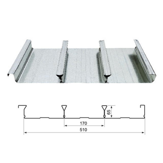
Selecting the correct profile geometry is essential for aligning structural performance with project requirements. Different architectural demands have driven the engineering of distinct profiles. To make field selection easier, let us look at how different geometries stack up against each other.
Profile Type | Typical Span Range | Key Structural Advantage | Best Application |
|---|---|---|---|
Open-Type | 6 to 10 feet | Cost-effective, excellent shear bond | Standard Commercial Offices |
Closed-Type | 8 to 12 feet | Flat soffit, high vibration dampening | Petrochemical & Heavy Industrial |
Steel Truss | 12 to 16+ feet | Self-supporting, eliminates shoring | Logistics Centers & Warehouses |
The open-type profile features a traditional trapezoidal ribbed design. It remains the most widely manufactured geometry in the industry. Wide flutes allow maximum concrete volume in the ribs to create a strong shear bond. When specifying for standard industrial layouts, a high-quality steel floor bearing plate like the HY-51-250-750 offers an excellent balance. With a 51mm rib height and 750mm effective width, it delivers structural stiffness without excessive material weight.
In contrast, closed-type decking utilizes a dovetail or tightly closed rib design. This geometry creates a virtually flat soffit while maintaining deep internal flutes for concrete interlocking. The dovetail shape allows for the easy installation of hanger wedges to suspend pipes directly from the ceiling. For harsh environments requiring robust performance, a closed-profile steel deck panel such as the YXB-65-185-555 provides exceptional fire resistance. Its 65mm depth and 555mm coverage width make it highly resistant to dynamic industrial vibrations.
For extreme demands, load-bearing steel truss profiles represent an advanced composite system. Steel reinforcement bars are pre-welded into a three-dimensional truss framework directly onto a flat galvanized base sheet. By integrating the rebar prior to installation, a load bearing floor deck delivers immense rigidity during the construction phase. This effectively eliminates the need for temporary shoring in ultra-long span applications.
Looking at broader construction sector movements, there is a distinct shift toward performance-based specifications. Modern construction projects are moving away from traditional mild steel and increasingly utilizing high-tensile steel alloys. These advanced materials allow newer profiles to push traditional span limits significantly further without adding unnecessary dead weight to the building foundation.
This trend is particularly evident in the rapid expansion of automated e-commerce distribution centers. Facilities utilizing Automated Guided Vehicles require massive, uninterrupted floor spaces with minimal structural columns. Engineers are now prioritizing ultra-long span, shoring-free truss systems to accelerate construction timelines. Eliminating the weeks spent erecting and dismantling temporary supports directly translates to faster facility commissioning and lower overhead labor costs.
A common dilemma in structural design is balancing upfront material costs against on-site labor costs. Is it more economical to specify a thinner 22-gauge deck but pay for the labor to install temporary shoring? Or should you invest in a thicker 18-gauge deck that spans the distance unshored?
In most modern scenarios, the high cost of skilled labor makes the thicker gauge the superior financial choice. Eliminating shoring keeps the floor below clear. This allows mechanical, electrical, and plumbing trades to begin their work immediately.
While precise engineering calculations are mandatory, a general rule of thumb applies to gauge selection in the field. Light loads and short spans up to 6 feet can often utilize 22-gauge. Standard commercial loads spanning 6 to 10 feet typically rely on 20-gauge for a reliable balance of cost and performance. For heavy industrial loads or spans pushing beyond 12 feet, 18-gauge or 16-gauge is absolutely required to prevent deflection.
Beyond span capabilities, gauge heavily impacts job site durability. Before the concrete is poured, the bare panels must withstand severe abuse. Workers walking, heavy tool carts rolling, and concrete hoses dragging across the surface can easily dent thinner materials. Utilizing robust steel floor decking panels ensures the structural integrity of the profile remains intact before the floor is even finished.
Proper specification is only half the equation. Correct field execution is critical. If a project architectural design dictates a beam spacing that exceeds the deck maximum unshored span limit, temporary shoring is mandatory.
Shoring consists of temporary beams and posts installed beneath the deck. Best practices dictate that it must remain in place until the concrete reaches at least 75 percent of its design strength. This typically takes 7 to 14 days depending on weather conditions. Stripping shoring too early transfers the dead weight of partially cured concrete onto the steel. This leads to micro-fractures in the slab and severe long-term deflection.
The attachment method also impacts the building diaphragm shear strength. Traditional puddle welding involves melting a hole through the deck into the supporting beam. While effective, it requires certified welders and dry conditions. Mechanical fasteners, such as powder-actuated pins or self-drilling screws, are increasingly popular. They are faster to install, weather-independent, and provide highly consistent shear values without the risk of visible burn marks.
Choosing the right profile is a precise balancing act between span distance, concrete depth, and steel gauge. A thorough understanding of how these factors interact allows you to optimize structural safety while keeping project timelines and budgets firmly in check.
Always consult a licensed structural engineer for your specific project requirements. Rely strictly on certified manufacturer span tables rather than estimation. By aligning your facility unique load demands with the correct geometric profile, you ensure a durable and efficient build.
Stop guessing with your structural spans. Explore our high-performance decking solutions at Hongye Steel Structure today. Contact our engineering team to find the exact profile match for your next commercial or industrial project.
The primary difference lies in the surface design. Floor decking features mechanical embossments—small indentations rolled into the webs and flanges. These interlock with the poured concrete as it cures, creating unified composite action. Roof decking is typically smooth, lacks these embossments, and is only designed to support rigid insulation and roofing membranes.
The unshored span is the maximum distance a deck can stretch between structural supports while safely carrying the weight of wet concrete, construction crews, and equipment. If the distance between beams exceeds this limit, temporary vertical supports must be installed underneath until the concrete fully cures.
No. Pouring thicker concrete actually has the opposite effect during the construction phase. Wet concrete is extremely heavy. Adding more concrete increases the dead load on the deck before it cures, which decreases the allowable unshored construction span. To support thicker concrete over a long span, you must increase the deck gauge thickness or utilize a deeper profile.
Industry standards typically limit live load deflection to L/360, where L is the span length. For example, a 10-foot span cannot deflect more than one-third of an inch under normal operating loads. Strict adherence to these limits prevents the concrete slab from cracking and ensures the floor does not bounce uncomfortably under foot traffic or machinery.
Fire ratings are heavily dependent on the thickness of the concrete cover above the steel flutes. Closed-type profiles often achieve higher fire ratings with less overall concrete because their narrow top openings protect the concrete mass better during extreme heat exposure. Open-type profiles may require a thicker overall slab to achieve the same 2-hour or 3-hour fire rating.

